Making as a Way of Thinking – In Two Places


Jan 29, 2009


BAC Spring 2009 Studio


Resources


PROGRAM
Forge Area 1,152 sf
(12) forge workplaces approximately 8’x12’ each. Each workplace may have a forge and flue, or 2 workplaces may share a forge and flue. Forges are fueled with coal.
Common Fabrication Area 3,000 sf
adjacent to forge workplaces. In this space are located shared pieces of equipment such as compression hammer, grinders, cutting tools, etc. Connections for power, compressed air and gas.
Welding Area 600 sf
adjacent to common fabrication area. Benches, grinders, power and gas connections
Tool Room 240 sf
for storage and check out for tool use daily
Office 200 sf
(2) @ 120 sf each, for resident artist and studio manager
Toilet
male: 1 wc, 1 urinal, 2 lavatories, shower 200 sf
female: 2 wc, 2 lavatories, shower 250 sf
Sand Blasting Area
should be remote from main building 200 sf
Coal Storage
can be remote from main building 200 sf
Mechanical Compressor Room
generates compressed air 800 sf
Classroom
for instruction, sketching, critiques 800 sf
Circulation Area
Allowance 1,200 sf
Covered Loading Dock 200 sf
Total 8,152 sf
Outdoor Areas*
Porches for working
Porches for relaxing
Outdoor Metal Storage
* areas to be determined by designer
OTHER
Overhead Crane
for lifting items up to 5 tons
Daylight, Fresh Air
see notes for a sustaining studio
Construction
the building should be durable
and fire resistant.
A SUSTAINING STUDIO
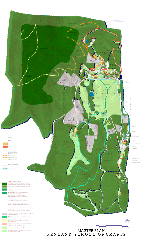
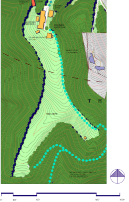
Students may pick anywhere in the cleared meadow to
place their building. A goal of the project is to protect
and conserve the landscape of the Black and Roan
Mountains where Penland is located. Expansive views
are available from the site. How do we build in a way
that enhances the environment? For centuries
Southerners have summered in the mountains to
escape the sultry heat of the lowlands. Cool breezes in
spring, summer and fall can ventilate the studio and
eliminate the need for air-conditioning. Rainwater is
plentiful, 50 inches per year, but precious. Rainwater
harvesting is a possibility. Covered outdoor work areas
can provide shelter from the rain.
PRESENTATION REQUIREMENTS
SITE PLAN—showing the structural and spatial organization
and its interface with the surrounding context.
ROOF PLAN—showing the serial and tectonic
character of the program components.
ARCHITECTURAL PLANS—showing all program
elements, , structure, circulation, and spaces.
ARCHITECTURAL SECTIONS AND ELEVATIONS—
location(s) of cut-throughs at designer’s discretion.
THREE-DIMENSIONAL IMAGES—two minimum
required.
DIAGRAMS—showing interrelationship of the
program components, facility types, and spaces.
ADDITIONAL IMAGES—at designer’s discretion
Develop and Present all drawings at a legible size and
scale, in relation to design intent, and keeping with
requirements for presentation.
FORMAT
Entries must be presented in the form of an 11" x 17"
booklet with horizontal orientation and firmly bound
with plastic binder strip on left 11" side. Carefully edit
your presentation to include only the essential content.
The Design Solution Summary described below is to be
integrated into your presentation booklet. The concepts
described must be clearly visible in your drawings and
supplemented by your narrative. Presentation techniques
used should always be subordinate to the ideas
communicated. Maximum of 6 pages plus cover. A page
is defined as one side of a sheet. Your presentation is to
be submitted and will be judged in hard copy format. To
assist in archiving and publication of entries, you must
also submit a copy of your presentation in electronic
format (.jpg) on a compact disc.
Each 11" x 17" page at 150 dpi (RGB preferred.)
DESIGN SOLUTION SUMMARY
A brief text of no more than 288 words may accompany
the drawings, describing the most important features
of your design solution.
A Blacksmithing Studio at Penland North Carolina
“Don’t ask me about this building or that one, don’t look at what I do, see what I see.” Luis Barragán